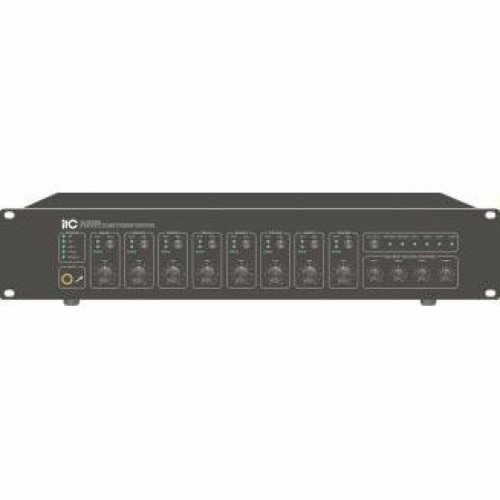
Descriptions
VA-P8500S of 2RU case, with built-in 500W digital amplifier and 8 independent power zones, which can be installed in the broadcasting room or remote control room, share the network audio source with the system via the internet (Includes the EVAC message and network back ground music), support 4 local line inputs (The priority can be set from the main controller), is the ideal unit for setting up medium or small applications.
Features
Support the speaker loop ground connection, open circuit and short circuit test detection.
Support the speaker loop cabling of 3 wire or 4 wire.
8 Programmable online input trigger interfaces
8 Programmable online output trigger interfaces
Support power saving mode when no signal input.
Support the line redundant wiring
Support linkage fire alarm controller and realize fire alarm linkage control
Basic Functions
* With built-in 500W digital amplifier and 8 outputs, LED indicator for each zone, independent output control button and volume control.
* Network EVAC input and BGM input, local emergency mic input, business mic input and 2 line inputs; User can set the priority of the mic in VA-6000ST.
* Can work with 1 extra standby amplifier, when the built-in amplifier come out fautly, the standby amplifier take over automatically.
* Automatically detection on the speaker loop (Ground connection, open circuit, short circuit).
* 8-CH dry and wet input interfaces, can trigger the pre-set voice messages distributed to different zones.
* 8 programmable relay signals output port, can output short circuit voltage control signal to a third party device to realize online automatic control.
* Support 24V DC input interface (To connect the 24V DC supplied by VA-6000BC).
VA-P8500S Front Panel <<

Connectors
1 19' Cabinet installation holes.
2 Zone amplifier main power indicatior:
(1) OFF - Amplifier not working.
(2) GREEN - Working.
(3)YELLOW - Main power supply fault.
3 Zone amplifier DC 24V power indicator:
(1) OFF - No standby power supply offered
(2) GREEN - Standby power supply working properly
(3) YELLOW - Standby power supply fault
4 Zone amplifier working status indicator. (If without the standby amplifier, it only display the status of main amplifier):
(1) OFF- Both main amplifier and standby amplifier working properly.
(2) YELLOW - The main amplifier or standby amplifier faulty.
5 Main status of the zone amplifier indicatior:
(1) GREEN - Zone amplifier working properly.
(2) YELLOW - Faulty.
6 Audio signal indicator, for displaying the current audio output status of the zone.
7 Emergency MIC interface.
8 Output status indicator:
(1) OFF - The current zone off.
(2) GREEN- The current zone is working and outputting normal audio signal.
(3) RED - The current zone is working and outputting EVAC messages or remote paging such as RM/FM/PSTN.
9 Zone status LED 3-color indicator:
(1) OFF - Working.
(2) YELLOW - Fault (Open circuit, short circuit and Ground connection).
10 Volume control knob (Only for normal BGM, not for EVAC messages or remote paging messages).
11 Zone select buttons.
12 All output button.
13 MIC 1 Output control.
14 Network evacuation voice message indicator :
(1) OFF - No network EVAC audio.
(2) GREEN - EVAC audio broadcasting.
15 MIC 2 Volume control.
16 Network BGM indicator:
(1) OFF - No Network BGM audio.
(2) GREEN - Network BGM audio broadcasting.
17 MIC 1 indicator:
(1) MIC1 - OFF - MIC 1 OFF.
(2) GREEN - MIC 1 ON.
18 Volume control for Line input 1.
19 MIC 2 indicator:
(1) OFF - MIC 2 OFF.
(2) GREEN - MIC 2 ON.
20 Volume control for Line input 2.
21 Line input 1 indicator:
(1) OFF - No signal in line input 1.
(2) GREEN - With signal in line input 1.
22 Line input 2 indicator:
(1) OFF - No signal in line input 2.
(2) GREEN - With signal in line input 2.

1 8-CH 100V signal output, to connect 3 wire/4 wire volume control or speaker.
2 Parallel audio signal and standby signal output to the standby power amplifier, to the input of the standby amplifier.
3 100V signal input to standby amplifier.
4 8-CH programmable relay trigger signal.
5 8-CH programmable trigger input signal. (Level signal or short circuit signal can be configurated).
6 2 line input signal interfaces.
7 Normal MIC ( or the line input for the audio sources).
8 Equipment linkage interface.
9 CAN main cable interface, to connect the recharger. (VA-6000BC).
10 Standby power supply input ( To connect DC 24 power supply, that is output of VA-6000BC in this system ).
11 Ground connection spot ( Note: Please ensure this connect to the ground safely ).
12 Power switch and input of the power supply with fuse.
Specifications
Model | VA-P8500S |
AC power |
|
Voltage | ~ 230V, 50/60Hz |
Mimum current | 3A (Exclude the 4 wire override output) |
Fuse Data | 250V/5A, Slow type |
DC Power | DC Power |
Voltage | 24V DC, ¡À20% |
Mimum current | 25A (Exclude the 4 wire override output) |
Power consumation | 600W |
Performance Index |
|
Line input |
|
Distortion | <1% (RMS), 1kHz |
Frequency | 80Hz~20kHz |
Sensitivity | 350mV |
Impedance |
Etiketler:
8 Zone Voice Alarm Amplifier VA-P8500S |

